

A recent post re-introduced the idea of connecting speaker loads using both standard (stereo/dual) connection and bridge tied load in a single implementation. The given elements are:
all three speaker loads are 8 ohms
one of the speakers will receive 6db greater signal
the amplifier will “see” a 4 ohm load as the amp is bridgeable to 4 ohms
If you haven't practiced doing these computations, the steps are all broken out and the work is shown.
Here is the original proposed schematic solution:
View attachment 16149
If you don't have your Ohm's law and power calculations memorized find a power wheel cheat sheet here:
View attachment 16153
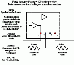
In order to analyze the current, power and load on an amplifier we will make some assumptions. The original solution stipulates a 6db greater amplitude for the bridged tied load. To provide an easy to understand power relationship the normally connected speaker pair will be set at a very typical 100 watts each. Now let's calculate the current and voltage.
View attachment 16150
Piece of cake right? Drop in the numbers and we find 3.54 amps of current will flow when 100 watts are dissipated in the load. The amplifier will have 28.28 volts at it's terminal (let's call it V term) when doing so.
View attachment 16151
Under the same conditions, the same V term, what are the conditions in a bridged load (BTL or Bridge Tied Load). The amplifier must have the capability of being bridged. To do so the amplifier must be able to drive both sides with the same signal and invert the output of one side (usually #2). What this means is that whatever signal is output on one side, it's mirror image is produced on the other. If one side outputs +2 volts the mirror outputs -2 volts. As one terminal swings up in voltage the other swings down and vice versa. Each terminal of the BTL puts out half the voltage [differential] to the load. As a result, the voltage across the load is also doubled. If voltage is doubled and resistance remains the same, the current is doubled as well. With voltage and current doubled the power dissipated in the load is now 4X higher than in a single load run off one side of the amplifier.
Remember that connecting an amplifier in BTL extracts no more power than two normal loads sized for maximum power transfer. The maximum BTL load is half that ( two times more resistance) of a normally connected load.
It may help to imagine an electrical center or balance point in the BTL load. At the center point electrically mid-way between the two terminals, the voltage is always zero as either side's voltage swings up or down in unison with its respective terminal. Think of one side pushing and the other pulling. When the current reverses again, the same side is pulling and other pushing.
The current in all parts of a series circuit is the same. While each terminal of the BTL supplies only half the voltage, each terminal supplies the same current. When only the BTL load is present, the current at both terminals must be the same. Under normal BTL conditions this is the case. Standard textbook and instruction manual descriptions depict the load connected only to the two hot terminals.
View attachment 16152
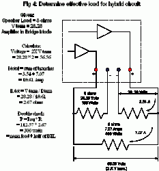
This is what you've been waiting for, the final load calculation. Kirchoff says that the total current is equal to the sum of the branch currents. Both amplifiers have two paths for current. One path is shared with the other positive terminal (7.07 Amps) and the second path returns to the low terminal on the same side of the amplifier (3.54 Amps). The total current flowing from each terminal is 10.61 amps. The resistance = the voltage at the terminal / total current = 2.67 ohms.
To double check the figures, square the current and multiply it by the calculated resistance = 112.57 * 2.67 = 300. This is all of the normally connected load and half the BTL.
A final word on BTL and the possible 6db increase of output. In the hybrid configuration shown in fig 1, the BTL load will always be driven with 6db more signal than the normally configured loads. But how does this fit the power curve of your amplifier? The power capability of an amplifier will follow a curve which rises as the load impedance decreases, roughly following ohm's law. Below a certain load impedance, output falls, in some cases steeply. Where this occurs will vary from amp to amp but will most certainly occur below the amplifier's minimum output impedance . Many amplifiers may be capable of driving 2 ohm loads but often at a reduced power rating. The 6db of additional drive you might be expecting will not be available as the output falls attempting to drive a load at an impedance lower than it was designed for. Distortion figures will suffer, the amp may overheat and in the worst case situation, fail completely. Super amplifiers do exist that will drive very low impedance loads but they are more rare than common and certainly more expensive. Be aware of where on the load impedance / power output curve your configuration will be before assuming your configuration can benefit from a BTL configuration.
in } P { margin-bottom: 0.08in } -->
all three speaker loads are 8 ohms
one of the speakers will receive 6db greater signal
the amplifier will “see” a 4 ohm load as the amp is bridgeable to 4 ohms
If you haven't practiced doing these computations, the steps are all broken out and the work is shown.
Here is the original proposed schematic solution:
View attachment 16149
If you don't have your Ohm's law and power calculations memorized find a power wheel cheat sheet here:
View attachment 16153
In order to analyze the current, power and load on an amplifier we will make some assumptions. The original solution stipulates a 6db greater amplitude for the bridged tied load. To provide an easy to understand power relationship the normally connected speaker pair will be set at a very typical 100 watts each. Now let's calculate the current and voltage.
View attachment 16150
Piece of cake right? Drop in the numbers and we find 3.54 amps of current will flow when 100 watts are dissipated in the load. The amplifier will have 28.28 volts at it's terminal (let's call it V term) when doing so.
View attachment 16151
Under the same conditions, the same V term, what are the conditions in a bridged load (BTL or Bridge Tied Load). The amplifier must have the capability of being bridged. To do so the amplifier must be able to drive both sides with the same signal and invert the output of one side (usually #2). What this means is that whatever signal is output on one side, it's mirror image is produced on the other. If one side outputs +2 volts the mirror outputs -2 volts. As one terminal swings up in voltage the other swings down and vice versa. Each terminal of the BTL puts out half the voltage [differential] to the load. As a result, the voltage across the load is also doubled. If voltage is doubled and resistance remains the same, the current is doubled as well. With voltage and current doubled the power dissipated in the load is now 4X higher than in a single load run off one side of the amplifier.
Remember that connecting an amplifier in BTL extracts no more power than two normal loads sized for maximum power transfer. The maximum BTL load is half that ( two times more resistance) of a normally connected load.
It may help to imagine an electrical center or balance point in the BTL load. At the center point electrically mid-way between the two terminals, the voltage is always zero as either side's voltage swings up or down in unison with its respective terminal. Think of one side pushing and the other pulling. When the current reverses again, the same side is pulling and other pushing.
The current in all parts of a series circuit is the same. While each terminal of the BTL supplies only half the voltage, each terminal supplies the same current. When only the BTL load is present, the current at both terminals must be the same. Under normal BTL conditions this is the case. Standard textbook and instruction manual descriptions depict the load connected only to the two hot terminals.
View attachment 16152
This is what you've been waiting for, the final load calculation. Kirchoff says that the total current is equal to the sum of the branch currents. Both amplifiers have two paths for current. One path is shared with the other positive terminal (7.07 Amps) and the second path returns to the low terminal on the same side of the amplifier (3.54 Amps). The total current flowing from each terminal is 10.61 amps. The resistance = the voltage at the terminal / total current = 2.67 ohms.
To double check the figures, square the current and multiply it by the calculated resistance = 112.57 * 2.67 = 300. This is all of the normally connected load and half the BTL.
A final word on BTL and the possible 6db increase of output. In the hybrid configuration shown in fig 1, the BTL load will always be driven with 6db more signal than the normally configured loads. But how does this fit the power curve of your amplifier? The power capability of an amplifier will follow a curve which rises as the load impedance decreases, roughly following ohm's law. Below a certain load impedance, output falls, in some cases steeply. Where this occurs will vary from amp to amp but will most certainly occur below the amplifier's minimum output impedance . Many amplifiers may be capable of driving 2 ohm loads but often at a reduced power rating. The 6db of additional drive you might be expecting will not be available as the output falls attempting to drive a load at an impedance lower than it was designed for. Distortion figures will suffer, the amp may overheat and in the worst case situation, fail completely. Super amplifiers do exist that will drive very low impedance loads but they are more rare than common and certainly more expensive. Be aware of where on the load impedance / power output curve your configuration will be before assuming your configuration can benefit from a BTL configuration.
in } P { margin-bottom: 0.08in } -->