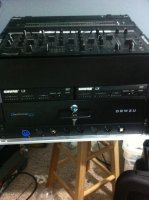


I decided to add the Instructions here on making a harness for your components in your Rack.
1. The Cables.Length
Determine the shortest correct length possible from the output of one component to the input of the other component.
Here is how.Looking from the back: Lets say the first component is on top and the other component is 3 spaces down (5.25")
Component #1's connection point is 5" from the right wall of the cabinet and component #2's connection point is 4" from the right wall of the cabinet
it will take about :Add the following to get the result
3" coming out from Component #1's connection point to make a right angle turn
+ 5" turn right to wall
+ 5.25" down the wall
+ 4" turn left to component #2
+ 3" to make a right angle turn to Component #2's connection point
= 20.25" or a 2' cable (Custom made or order a 2' or 3' ready made cable)
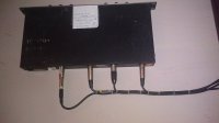
2. The breakouts:
If you have 2 pairs of connections on the back of a component (Left and Right In & Left and Right Out) that will give you four breakout points.
Therefore the connection to the far left will be naturally longer (From side wall to component point)
You will then have 4 cables making a left turn from the right side wall together.
Start with a heavy duty tie wrap holding all four and add a tie wrap for each 3" around the bundle until you get to the first breakout.
Make a right angle turn with the one cable and plug it in to the first connection from the right.Place a tie wrap just before the bend and one just after the bend to keep the bundle going.
Repeat that step to the second breakout and also until you get to the last connection point.
Some components such as analog crossovers may have six or even more breakouts.
The cable coming from the connectors to the side wall should have no hang because the connection points, tie wrapped bundle and attachment to side wall will give it the strength to remain stable and rigid.
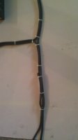
3. Side Wall/Channel: Cables running up/down side wall. You will need cable tie downs for the side wall to act as a holder for all signal cables running up and down the side wall. Remember to add tie wraps every 3' or so to keep the bundle stable. That whole area can be called your Channel up/down.
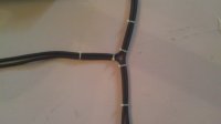
4. Junctions: There will be places where cables coming from a component on top meet with cables coming from a component on the bottom and both sets making a left turn to the same destination component. That is a junction point.There should be three heavy duty tie wraps at that point.One at the top of the joint, one at the bottom of the joint and one at the start of the left turn.
You may find yourself adding cables to a turn (coming from the wall) going to a component. until you have all cables connected to that component, you can place temporary tie wraps. When you are finished then permanently tie wrap.
Do not over tighten the tie wraps and do not use velcro wraps as those leave a play in the joints.
work from the top component downwards as cables will be hanging along the sidewall until permanently tie wrapped.
5. AC Cords: Run all AC cords to the opposite/left wall the same way you did the signal cables.
6. Markers: Buy label markers and identify your ends before you install or afterwards when everything is working. Examples of how to mark a cable end. EQ/In/Left or Xover/Out/Right
7. Materials: (You can buy these anywhere you want)
Tie Wraps:http://www.cabletiesandmore.com/cableties.php?gclid=CJCSqLrgvaoCFQtU7AodWxZl6A
Tie Clamps:http://www.cabletiesandmore.com/cable-clamps.php
Cable Tie Downs/Mounts (This is better when used with a screw): http://www.cabletiesandmore.com/adhesive-mounts.php
Cable Markers: http://www.cabletiesandmore.com/flag-cable-ties.php
If someone needs immediate help I can explain further by phone, just PM me first for my number.
Bundles should not be floppy.
If cables have excess, reloop and tie wrap on the channel bundle (Not on the end of the connectors)
I will add pics and diagrams to this post so look for updates.
1. The Cables.Length
Determine the shortest correct length possible from the output of one component to the input of the other component.
Here is how.Looking from the back: Lets say the first component is on top and the other component is 3 spaces down (5.25")
Component #1's connection point is 5" from the right wall of the cabinet and component #2's connection point is 4" from the right wall of the cabinet
it will take about :Add the following to get the result
3" coming out from Component #1's connection point to make a right angle turn
+ 5" turn right to wall
+ 5.25" down the wall
+ 4" turn left to component #2
+ 3" to make a right angle turn to Component #2's connection point
= 20.25" or a 2' cable (Custom made or order a 2' or 3' ready made cable)
2. The breakouts:
If you have 2 pairs of connections on the back of a component (Left and Right In & Left and Right Out) that will give you four breakout points.
Therefore the connection to the far left will be naturally longer (From side wall to component point)
You will then have 4 cables making a left turn from the right side wall together.
Start with a heavy duty tie wrap holding all four and add a tie wrap for each 3" around the bundle until you get to the first breakout.
Make a right angle turn with the one cable and plug it in to the first connection from the right.Place a tie wrap just before the bend and one just after the bend to keep the bundle going.
Repeat that step to the second breakout and also until you get to the last connection point.
Some components such as analog crossovers may have six or even more breakouts.
The cable coming from the connectors to the side wall should have no hang because the connection points, tie wrapped bundle and attachment to side wall will give it the strength to remain stable and rigid.
3. Side Wall/Channel: Cables running up/down side wall. You will need cable tie downs for the side wall to act as a holder for all signal cables running up and down the side wall. Remember to add tie wraps every 3' or so to keep the bundle stable. That whole area can be called your Channel up/down.
4. Junctions: There will be places where cables coming from a component on top meet with cables coming from a component on the bottom and both sets making a left turn to the same destination component. That is a junction point.There should be three heavy duty tie wraps at that point.One at the top of the joint, one at the bottom of the joint and one at the start of the left turn.
You may find yourself adding cables to a turn (coming from the wall) going to a component. until you have all cables connected to that component, you can place temporary tie wraps. When you are finished then permanently tie wrap.
Do not over tighten the tie wraps and do not use velcro wraps as those leave a play in the joints.
work from the top component downwards as cables will be hanging along the sidewall until permanently tie wrapped.
5. AC Cords: Run all AC cords to the opposite/left wall the same way you did the signal cables.
6. Markers: Buy label markers and identify your ends before you install or afterwards when everything is working. Examples of how to mark a cable end. EQ/In/Left or Xover/Out/Right
7. Materials: (You can buy these anywhere you want)
Tie Wraps:http://www.cabletiesandmore.com/cableties.php?gclid=CJCSqLrgvaoCFQtU7AodWxZl6A
Tie Clamps:http://www.cabletiesandmore.com/cable-clamps.php
Cable Tie Downs/Mounts (This is better when used with a screw): http://www.cabletiesandmore.com/adhesive-mounts.php
Cable Markers: http://www.cabletiesandmore.com/flag-cable-ties.php
If someone needs immediate help I can explain further by phone, just PM me first for my number.
Bundles should not be floppy.
If cables have excess, reloop and tie wrap on the channel bundle (Not on the end of the connectors)
I will add pics and diagrams to this post so look for updates.